DIY Ambilight + WS2812B + Arduino + Boblight for Windows
Hello everyone,
I write this post not only to show you my new Ambilight clone but especially hoping to save you the four days of madness that I spent working on this project, including failed attempts and various problems I had to solve.
Yes, Because Those Who decides to engage in this project will come across many headaches, as I myself have Dealt with, and Inevitably will pour on the forums into the sea of questions that are repeated.
I promise you that Following this guide and my resolutions to known problems, you will have an Ambilight clone running in less than 40 minutes. Do not believe me? Follow me and you will see. Let’s start!
List of components:
Hardware
- Led strip type WS2812B
- Arduino Mega
- Power supply stabilized 5V – 45A
Software
- Adafruit Neo Pixel library
- Arduino sketch for reading from serial and controlling LEDs
- Boblightd daemon for windows
- Boblight xbmc client
Arduino Side:
I assume That You Already have Followed this excellent guide to recognize the various types of LED strips, installed the hardware and successfully run the tests.
- “strandtest” from the library Adafruit Neo Pixel
- “Fire2012” and “ColorTemperature” from the library Fast_LED.
Tip: Do not bother with libraries LEDStream or Adalight as they are dedicated to chip WS2801 (4 pins) and use a communication protocol different from the WS2812 (3 Pins).
Make sure you have the library Adafruit_Neo_Pixel-master installed, load this sketch to your Arduino after making sure to change the following fields according to your needs:
DATAPIN: The pin number connected to your data_in of the LED strip.
LEDCOUNT: The number of LEDs used in your system, it’s the number of discrete LEDs present, not the number of RGB channels. Es: If you have 120 LEDs, it is 120.
BAUDRATE: Must be the same value specified in the file boblight.conf of boblightd daemon. If you do not have communications issues whatsoever leave the default value.
PREFIX: This sketch uses a series of 6 HEX numbers to recognize the beginning of each color frame.
Tip: Prefix is an arbitrary code, only make sure that you use the same code in both the Arduino sketch and the boblight.conf file. This means that this number does not depend neither on the type of the strip in use nor the number of LEDs, and must not be recalculated using any scripts in processing.
NEO_GRB, NEO_RGB, NEO_KHZ800, NEO_KHZ400: Depending on the chip of LED strip, read the comments in the Arduino sketch to know which one to use.
PC Side
So far you should not have had problems, but from this point on, due to different versions of boblight around, could begin the real headache.
Boblight is only available for Linux systems and you will need a version compiled to run on windows. Also numerous versions are incomplete, bugged and not working.
The version linked below is fully functional and modified by me to avoid some known issues.
Boblightd (daemon) + Boblight (XBMC client)
BOBLIGHTD
Extract the .rar archive to C:\
You will need your own boblight.conf file following your LEDs configuration.
In C:\boblightd\ you can find my version of the file, feel free to modify that file or just create a new one with this online tool.
First part of the config file is:
#[global]
interface 127.0.0.1
port 19333
[device]
name ambilight
type momo
output /dev/com3
channels 360
interval 5000
prefix 41 64 61 00 31 64
rate 460800
debug on
delayafteropen 1000000
Notes:
NAME: whichever you want.
TYPE: momo is right for WS2812B chipset.
OUTPUT: /dev/comx where x is the number of the port where Arduino is connected, look at control panel / devices management / ports (COM and LPT) to find out which one.
CHANNELS: number of total R+G+B channels, 3 * # LEDs. Es: with 120 LEDs, it is 360.
INTERVAL: capture refresh rate, 20000 is for one image captured every 50ms which is right for video application.
PREFIX: some arbitrary HEX numbers to make Arduino be able to find the start of each frame, It can be wichever combination you want, just change them in the Arduino sketch too accordingly.
RATE: baud rate, speed of serial communication. It must be the same specified in boblight.conf
DEBUG: on / off to activate verbose mode in cmd shell.
DELAYAFTEROPEN: Some delay after port opening.
Second part of the config file is pasted from the online tool:
[color]
name red
rgb FF0000
gamma 0.91
adjust 1.0
blacklevel 0.0
[color]
name green
rgb 00FF00
gamma 0.86
adjust 0.96
blacklevel 0.0
[color]
name blue
rgb 0000FF
gamma 0.95
adjust 0.8
blacklevel 0.0
[light]
name 001
color red ambilight 1
color green ambilight 2
color blue ambilight 3
hscan 0 10
vscan 0 20
[light]
name 002
color red ambilight 4
color green ambilight 5
color blue ambilight 6
hscan 0 10
vscan 4 20
etc…
BOBLIGHT
This is the client node for xbmc. Install this add-on from xbmc official repository called service “XBMC boblight”.
Ok, now we are ready to start the daemon with start.bat. You should see something like this:

Followed by this:

Known issues:
If you get any “Not a Valid Win32 Application” error message => It’s a bugged version => Download this one.
If you get “boblightd outputs ERROR:abmiligt: dev/com3: tcgetattr() invalid argument” and then: “ambilight dev/com3 had a non fatal error, it might still work” => This is due to how windows manage the COM ports, preventing ambilightd to successfully open the port in some situations, including new boot or reboot. I manage this by simply write a character to the serial port with the echo command, this seems to awake the port and make the deamon start as normal => Again download my modded version of the daemon to get rid of this issue.
Minimize the dos shell and run XBMC which It should says “connected to boblightd” at startup.
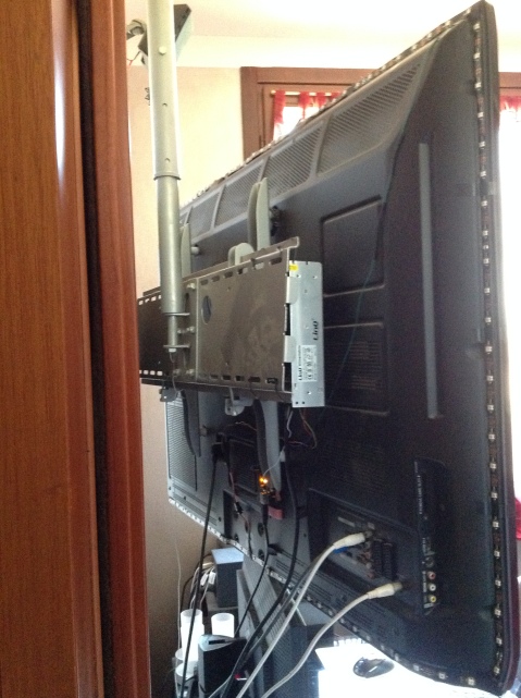
Play a movie and enjoy the show! Here is my results, sorry for the flickering but it’s a plasma TV.


Now, as promised, should be passed at the most 40 minutes and I’m sure I was able to solve at least one problem whose solution you’ll be panting to find on various forums.
If so leave a comment about your experience and maybe with a picture of your Ambilight system.
Have fun with your new multimedia system and goodbye to the next!
An FPGA implementation of Kalman Filter on Altera DE2
As promise, here is the complete project of an hardware implementation of the Kalman estimation algorithm on Altera DE2 board.
This time I made a video with a small presentation and demonstration of the project. Enjoy!
For those who are willing to go into that and chew a bit of Italian, here is the link to the report associated with the project:
Implementazione del fltro di Kalman su FPGA
Check below for the link at complete project materials
Download
Kalman Filter
I recently heard, from one of my professors of embedded systems, for a particular estimation algorithm called kalman filter. He told me that he was contacted by a company interested in implementing it in the process of measurement of the weight of products that run on the conveyor belt.
Well, I was not impressed until I found, rummaging in the literature, some interesting application…
The Kalman filter is named after its inventor, electrical engineer and mathematician Rudolf Emil Kalman that Published this technique in 1960. During kalman visit to NASA Ames Reserch Center, Schmidt saw the possibility to apply the idea of Kalman on the Apollo program that in those years was developing. The Kalman filter was incorporated into the navigation computer of each spacecraft of the Apollo program.
After this first application, the Kalman filter played a vital role in the military, in the implementation of the navigation systems of the missiles nuclear-tipped, ballistic submarines U.S. Navy, systems guidance and navigation of Tomahawk missiles, and Air Launched Missile Cruise.
In civil is still used for the driving control and navigation of NASA Space Shuttle and for the attitude control and navigation of the space station ISS.
For this discussion, Rudolf Emil Kalman, was awarded the National Medal of Science by U.S. President Barak Obama in 2008.
Wow, I thought that i did not want to miss this! So after some research here’s a little discussion about:
The Kalman filter invokes the more general problem of state estimation
x € R^n of a discrete-time process governed by stochastic differential equations
x k + 1 = A k x k + B k u k + w k
The estimation is performed by successive measurements z that:
z k = H k x k + v k
Where v k ,w k represent the process and measurement noises, assumed to be uncorrelated, white and with normal probability distribution with zero mean and variance, respectively Q and R.
p( w ) ∼ N( 0, Q )
p( v ) ∼ N( 0, R )
The matrices A k , B k e H k , are, respectively, the dependence of the current state from the previous state and the inputs (uk) and the extent of state.
Defined xk¯and xk the values of the a priori and a posteriori estimate and xk¯ and xk their predicted values, we calculate the estimation error as a priori and a posteriori as:
ek ¯= xk¯-xk¯
ek = xk –xk
Therefore we calculate the covariance a priori and a posteriori
Pk¯ = E[ek ¯ ek ¯ᵀ]
Pk = E[ek ek ᵀ]
We are looking for an equation that compute the a posteriori estimate xk as a linear combination of the a priori estimate xk¯ and the measurement of the difference between z k prediction of the measurement H k x k¯ weighted by a coefficient K
xk = xk¯ + K(z k – H k x k¯)
The origins of the probabilistic formula reside in the rule of Beyes that is, in a priori estimate of the state xk¯ conditioned by previous measurements z k.
The coefficient K is called the Kalman gain, and is chosen so as to minimize the covariance of a posteriori error.
A possible form that minimizes this covariance is
Kk = Pk¯ H k ᵀ * (H kPk¯ H k ᵀ+R)ˉ ¹
Expressing the covariance a posteriori
Pk = Pk¯ *(I + H k ᵀRˉ ¹H kPk¯)ˉ ¹
Through some simple matrix operations you can calculate the following expression of the gain of kalman ( to simplify keep Hk= 1 )
Kk = Pk * R ˉ ¹
From the above expression it is evident that the gain is directly proportional to the covariance and inversely proportional to the variance of the measurement error. You can interpret this fact by saying that the greater the error that you made in the previous estimate and the greater the refinement of the current estimate (gain) induced by the filtration, much less the measurements deviate from the real value, the more possible to obtain accurate estimates.
From the probabilistic point of view it is interesting to highlight how the filter maintains the first two moments
E[x k] = x k
E[(x k – x k) (x k – x k)ᵀ] = P k
The a posteriori state estimate reflects the average, while the a posteriori error covariance reflects the variance of the distribution of states.
Now that we have an idea of how it works, we can outline the steps to follow to implement the algorithm

The operations are divided into two groups: Time Update (Forecast) and Mesurement Update (Correction).
The Time Update operations provide a prediction of the current state and error covariance in order to obtain an a priori estimate of the next step.
The Mesurement Update operations are responsible for the feedback: they are used to join a new measurement with the a priori estimate to obtain a better a posteriori estimate.
The variances Q and R relate to the knowledge of the process that is being analyzed and the measuring system. The adjustment of these parameters can affect on the efficiency of the filter and is typically performed with other Kalman filters or otherwise outside of the algorithm that estimates the state of the process. It can however prove that once appropriately chosen Q and R, and that these remain constant, the covariance estimation P and the Kalman gain K stabilize in a certain number of cycles and then remain constants.
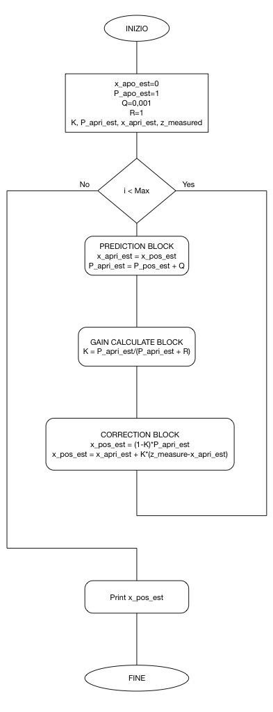
Here is the block diagram that I draw for my implementation.
I’m currently working of an FPGA implementation on Altera DE2 board of this algorithm to see what this algotirth can do with a good hardware, stay tuned for Verilog and C codes!
As always, below you can find the codes carefully discussed, of a possible implementation in Matlab and in C++ of this algorithm and some comparison between standard mean algorithms, and more below an odd but smart application 🙂 Hope you’ve enjoyed!!
Related articles
- Using a Kalman Filter to Predict Ticket Prices (chairnerd.seatgeek.com)
Electric door locking system with touchscreen
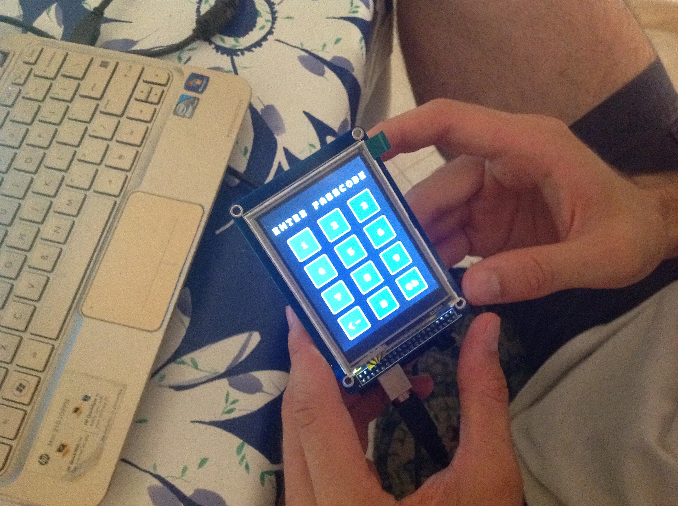
Hi, today i want to show you my last summer project…yeah i said summer, cause when the sun burns everything out there on 15th august, what’s better than an arduino mega with 3.2″ TFT touchscreen module to play with? Yes, i’m absolutely fool, but if you want to mess with this, here is my code to start!
For now it supports navigation between menus and the ability to change password, in a photo you can see a flowchart of a menu navigation and change password routine.
In the .rar you can find a link to the exact model of arduino i used, some manuals and useful LCD and SD libs and two different version of code:
- securecode: Bitmap version, it needs a copy of the content of “raw” directory on 2Gb SD card formatted in FAT32. The coolest but little slower.
I have hand-drawn bitmap icons inspired from iOS 6 color theme 🙂 then converted in raw format.
Check supplier site for SD compatibility list, i used one from an old satNav.
- securecode old style: Line graphics without SD support, faster and lightweight. Don’t need an SD card with bitmaps to be inserted.
Just out of the box the right passcode is “11111111” and type “00000000” to enter setup, enjoy!
I’m looking to add voice control capabilities in the future…
Feel free to hack my code and extend cool functionality, i’m waiting for your pimped versions or comments with new ideas!